may-august 2013
Well I am finally getting around to updating my blog with some new information from May through August 2013. Summer was busy. Sorry to anyone who was hungry for an update.
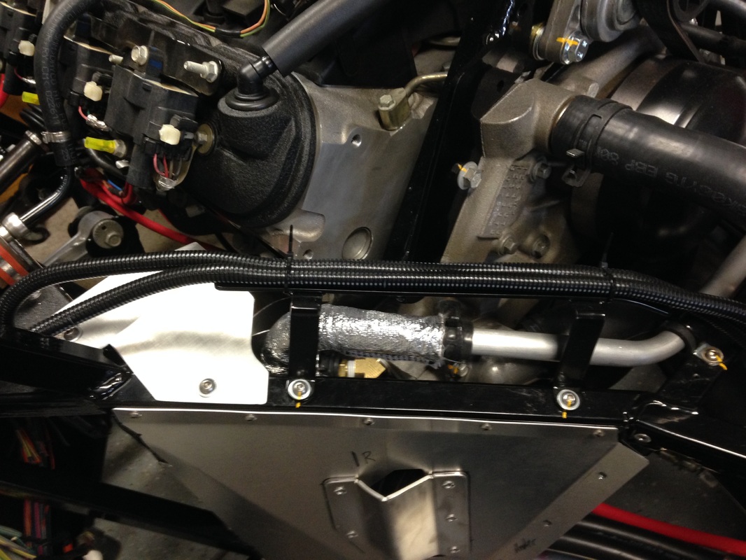
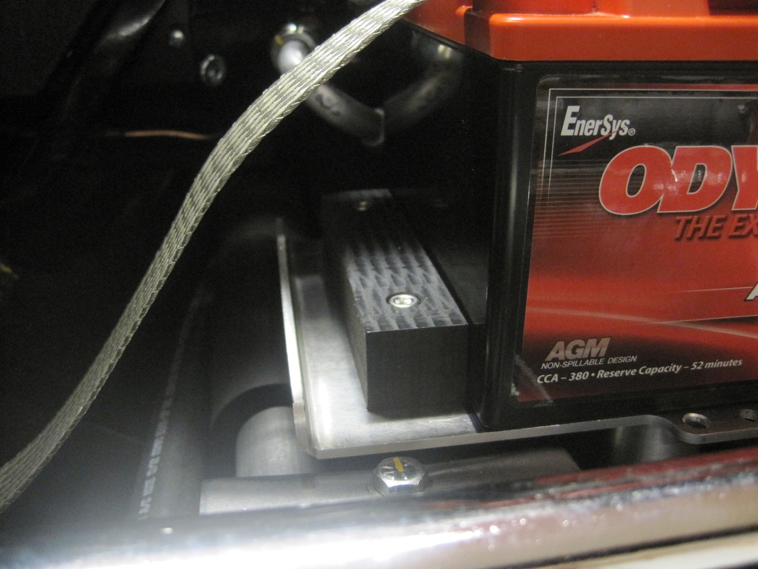
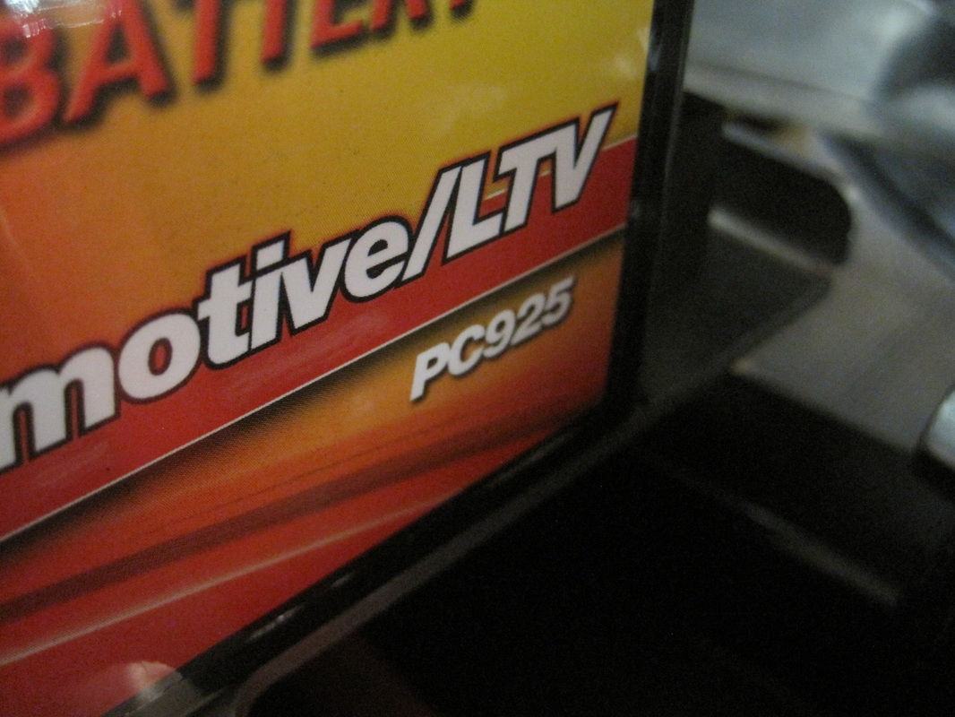
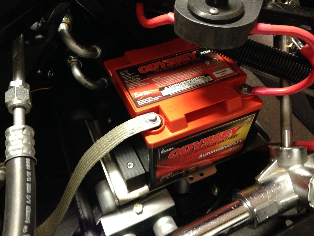
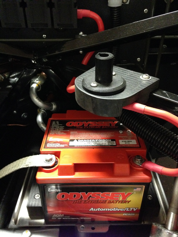
Elevated Battery Tray Continued
Since I elevated my battery to allow the cooling tubes to go under it I ended up with less room (height) for the battery. Not to worry....this was planned as I had seen a few builders using smaller batteries. After doing a little research, since there were a few choices, I ended up going with an Odyssey PC925 as they had good reviews. They use virgin lead (not recycled) and had good specifications for cranking up the LS1. The height of this battery worked well with the kit supplied battery hold down, it was the width of the battery that was more of a problem as the tray was much wider than the PC925 battery. To stop the battery from sliding around (imagine it sliding as your exceeding the recommended speed on a clover leaf) I made two UHMW blocks and bolted them to the tray just outside the battery dimensions. This worked out very well.

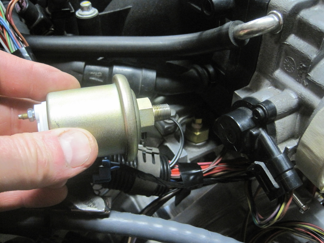
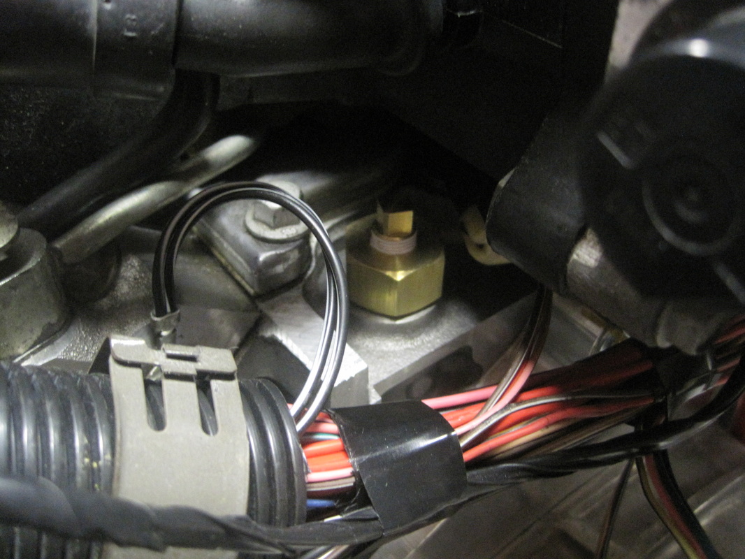
Oil Pressure Sending Unit
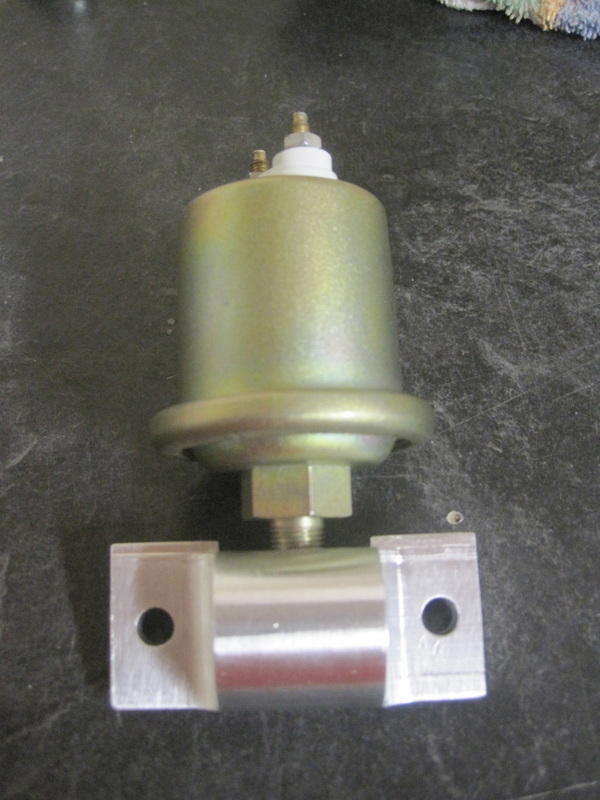
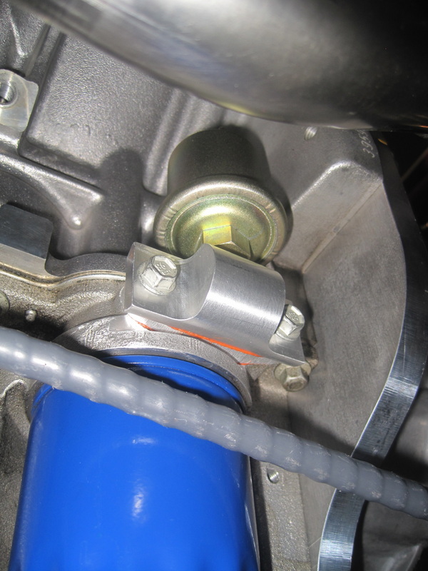
When I first looked at the location where FF has you mount the oil pressure sending unit I figured I needed to do something else. The stock location is cramped to say the least. I played with some different fitting arrangements to move it away from the intake and even looked at remote mounting it with a hose. None of these options seemed great. After some reading I found a few builders who had moved it to where the original pressure sensor was located. After a little searching I took some aluminum round stock to the Bridgeport and made a fitting that could bolt on at the original location but provide a 1/8" NPT port for the new sending unit. I simply plugged the old location on the top of the engine and was good to go.
When I first looked at the location where FF has you mount the oil pressure sending unit I figured I needed to do something else. The stock location is cramped to say the least. I played with some different fitting arrangements to move it away from the intake and even looked at remote mounting it with a hose. None of these options seemed great. After some reading I found a few builders who had moved it to where the original pressure sensor was located. After a little searching I took some aluminum round stock to the Bridgeport and made a fitting that could bolt on at the original location but provide a 1/8" NPT port for the new sending unit. I simply plugged the old location on the top of the engine and was good to go.
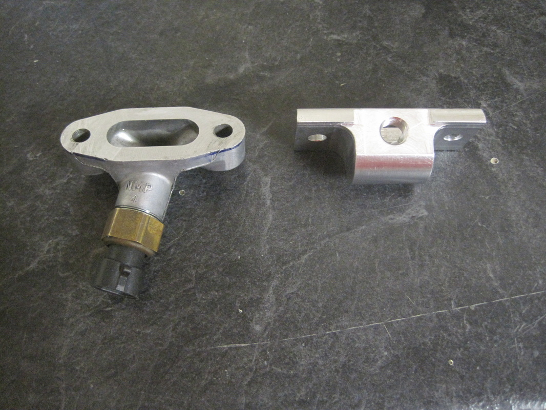
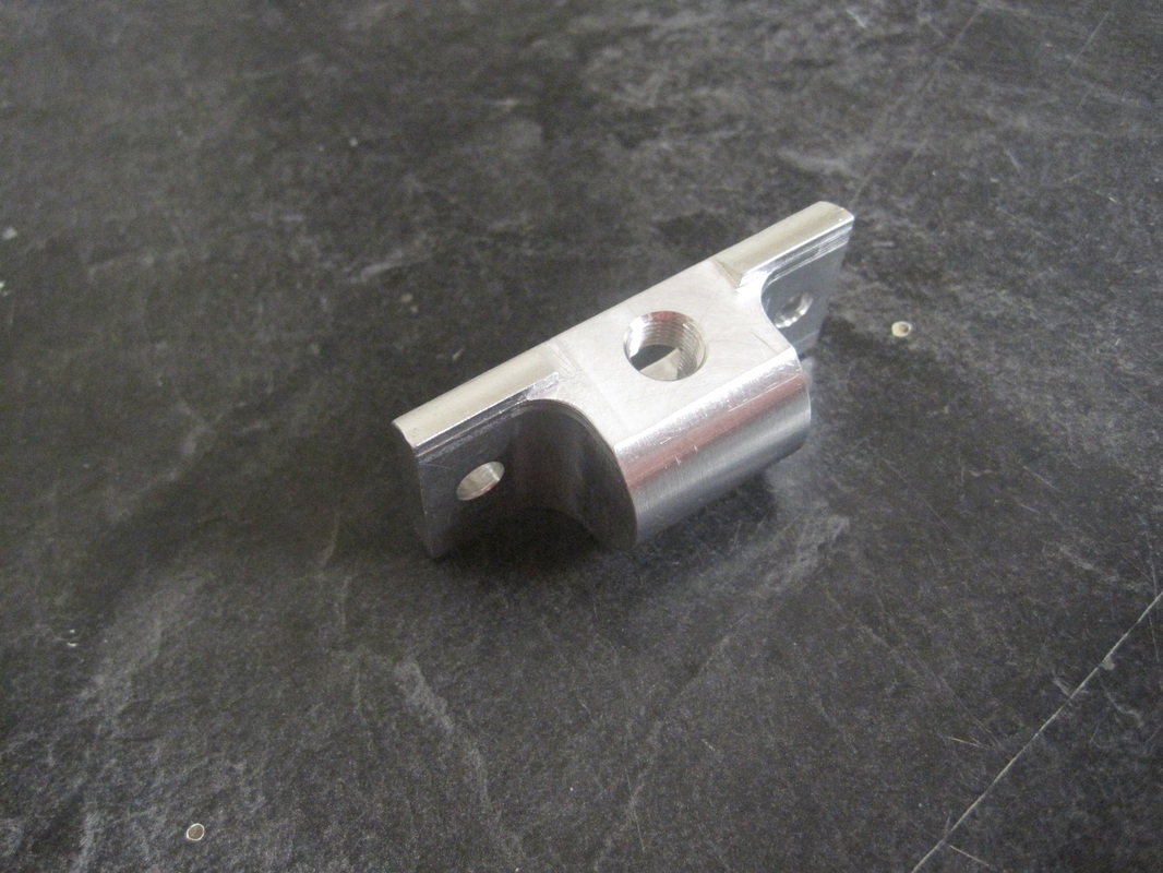
Starter Terminal
The manual has you run the battery cable from the front of the car to the C5 fuse panel and then from the fuse panel to the starter. After laying the cable in the car it seemed to work out better to run the longest battery cable from the battery directly to the starter and them from the starter up to the fuse panel. This kept the cable farther away from the headers and just looked like to be a cleaner installation. There was one problem though... if you attach the cable directly to the starter terminal it points straight up toward the passenger side drive shaft.. :-( After some head scratching I came up with the idea to machine the aluminum piece shown in the pictures below. This allowed the battery and fuse panel cable to point towards the front of the car. Win... win!!
The manual has you run the battery cable from the front of the car to the C5 fuse panel and then from the fuse panel to the starter. After laying the cable in the car it seemed to work out better to run the longest battery cable from the battery directly to the starter and them from the starter up to the fuse panel. This kept the cable farther away from the headers and just looked like to be a cleaner installation. There was one problem though... if you attach the cable directly to the starter terminal it points straight up toward the passenger side drive shaft.. :-( After some head scratching I came up with the idea to machine the aluminum piece shown in the pictures below. This allowed the battery and fuse panel cable to point towards the front of the car. Win... win!!


ISIS System
Prior to ordering my GTM kit I did tons of research on build options. One choice I made was to purchase an ISIS system. The ISIS system is a CAN bus network that replaces the Painless chassis harness included in the kit. It greatly simplifies wiring and allows modern features like push button starting, keyless entry, security, motor reversing without relays....etc. It is simply a must have if you want your car to have some modern features. When I ordered my ISIS three cell kit I also ordered a inmotion controller. The inmotion controller does DC motor reversing without any relays. Great for the windows and telescopic steering column.
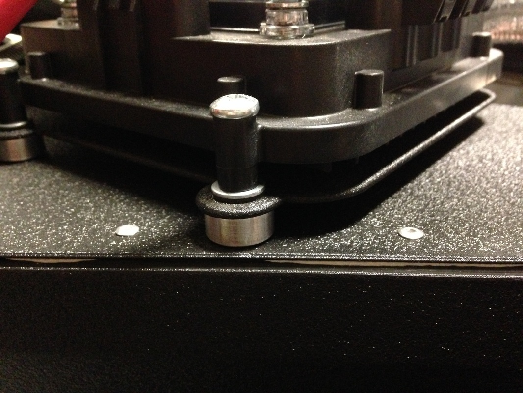
Module Mounting
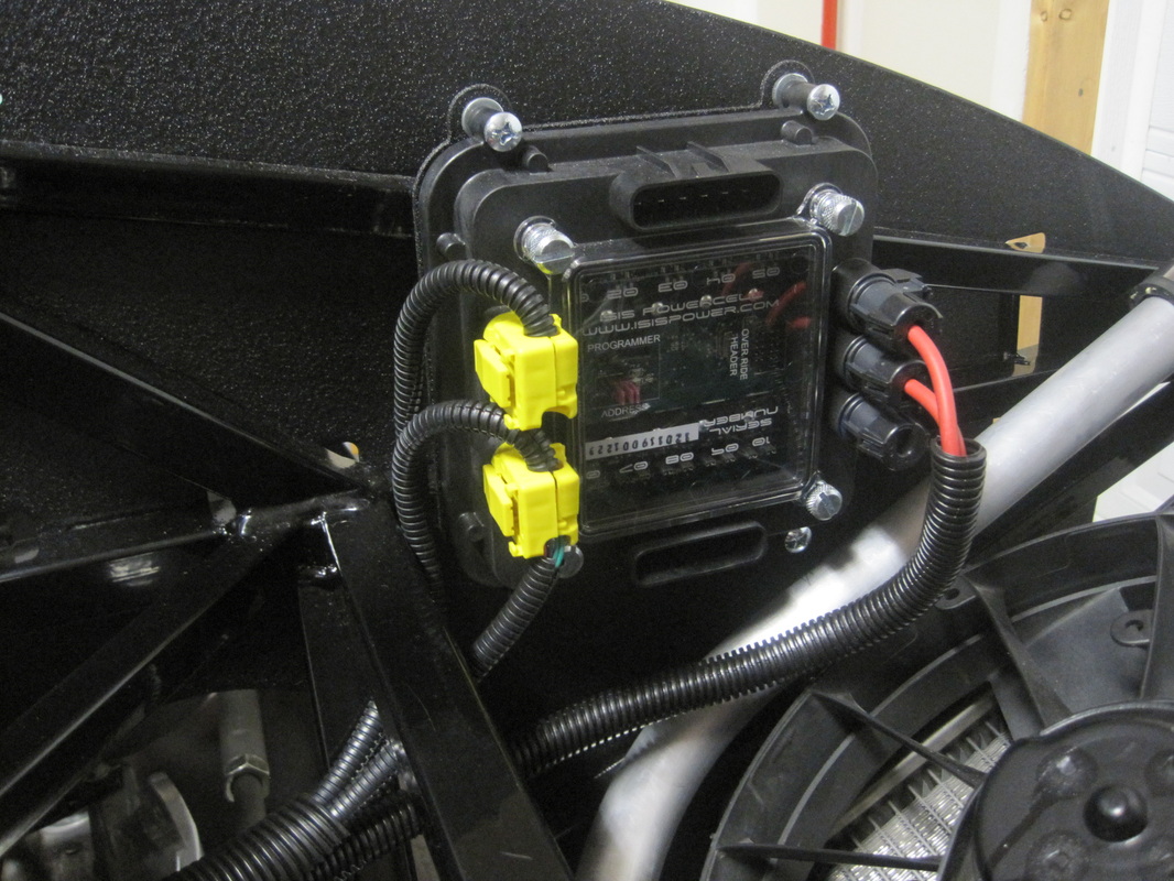
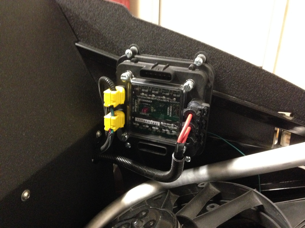
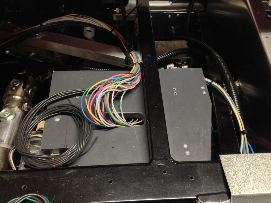
For mounting I purchased ISIS mounting plates from Shane at www.vraptorspeedworks.com. I bought the three cell mouting kit and one extra mount for the inmotion controller. I powder coated the two slave module mounts since they will remain visible. Pictures below show each of the mounted modules.
Prior to ordering my GTM kit I did tons of research on build options. One choice I made was to purchase an ISIS system. The ISIS system is a CAN bus network that replaces the Painless chassis harness included in the kit. It greatly simplifies wiring and allows modern features like push button starting, keyless entry, security, motor reversing without relays....etc. It is simply a must have if you want your car to have some modern features. When I ordered my ISIS three cell kit I also ordered a inmotion controller. The inmotion controller does DC motor reversing without any relays. Great for the windows and telescopic steering column.
Module Mounting
For mounting I purchased ISIS mounting plates from Shane at www.vraptorspeedworks.com. I bought the three cell mouting kit and one extra mount for the inmotion controller. I powder coated the two slave module mounts since they will remain visible. Pictures below show each of the mounted modules.


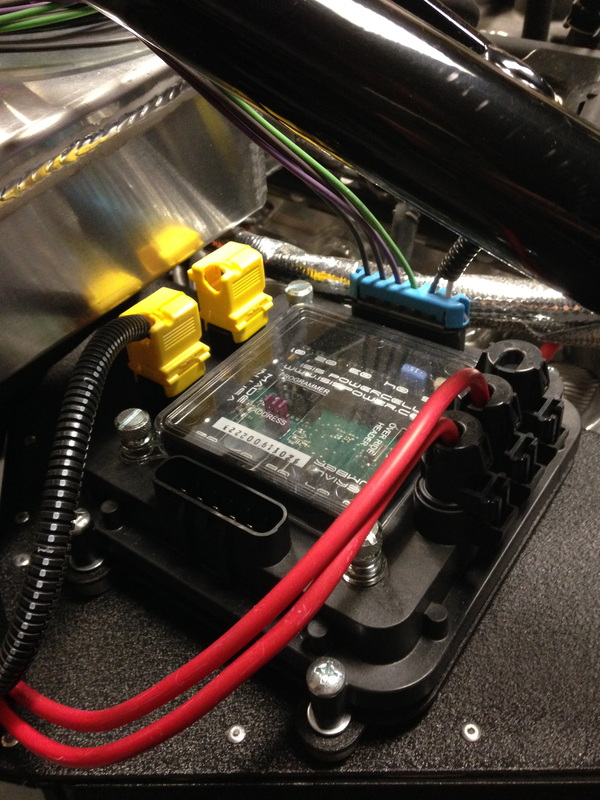
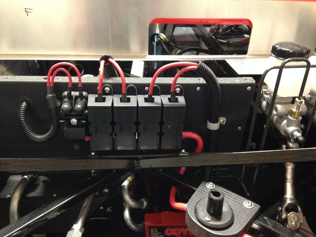
Running Power Wires & CAN Cables
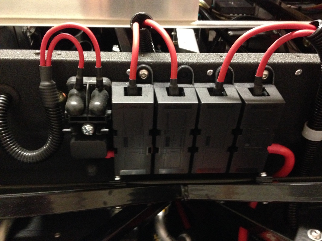
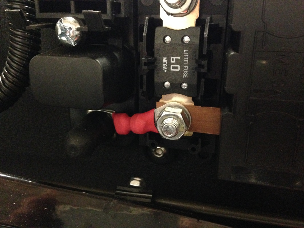
After mounting the modules they need some power (12V+). The ISIS system comes with mega fuses and wires for accomplishing this. After looking at some other build sites I decided to mount the fuses on the firewall and proceeded to run the wires to each module. Since the ISIS system draws current even when the vehicle is off I also added a master power switch between the battery and the mega fuses. This will allow me to cut all power to the system when I am not driving the car and prevent the battery from being completely discharged. Once the power wires were run I connected the CAN cables (yellow plugs) and the terminal resistor. Since I was using an InMotion controller my terminal resistor ended up in the InMotion controller. Below are some pics of the finished install.
After mounting the modules they need some power (12V+). The ISIS system comes with mega fuses and wires for accomplishing this. After looking at some other build sites I decided to mount the fuses on the firewall and proceeded to run the wires to each module. Since the ISIS system draws current even when the vehicle is off I also added a master power switch between the battery and the mega fuses. This will allow me to cut all power to the system when I am not driving the car and prevent the battery from being completely discharged. Once the power wires were run I connected the CAN cables (yellow plugs) and the terminal resistor. Since I was using an InMotion controller my terminal resistor ended up in the InMotion controller. Below are some pics of the finished install.


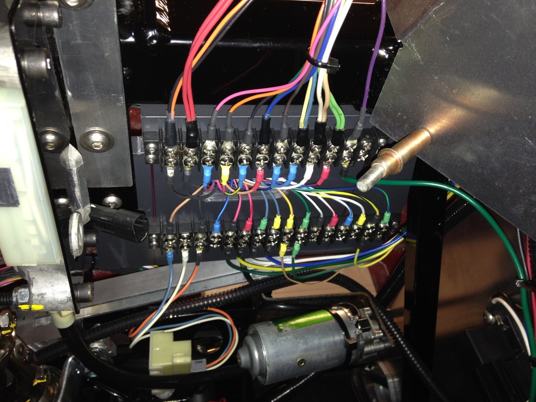
ISIS Inputs - Terminal Blocks
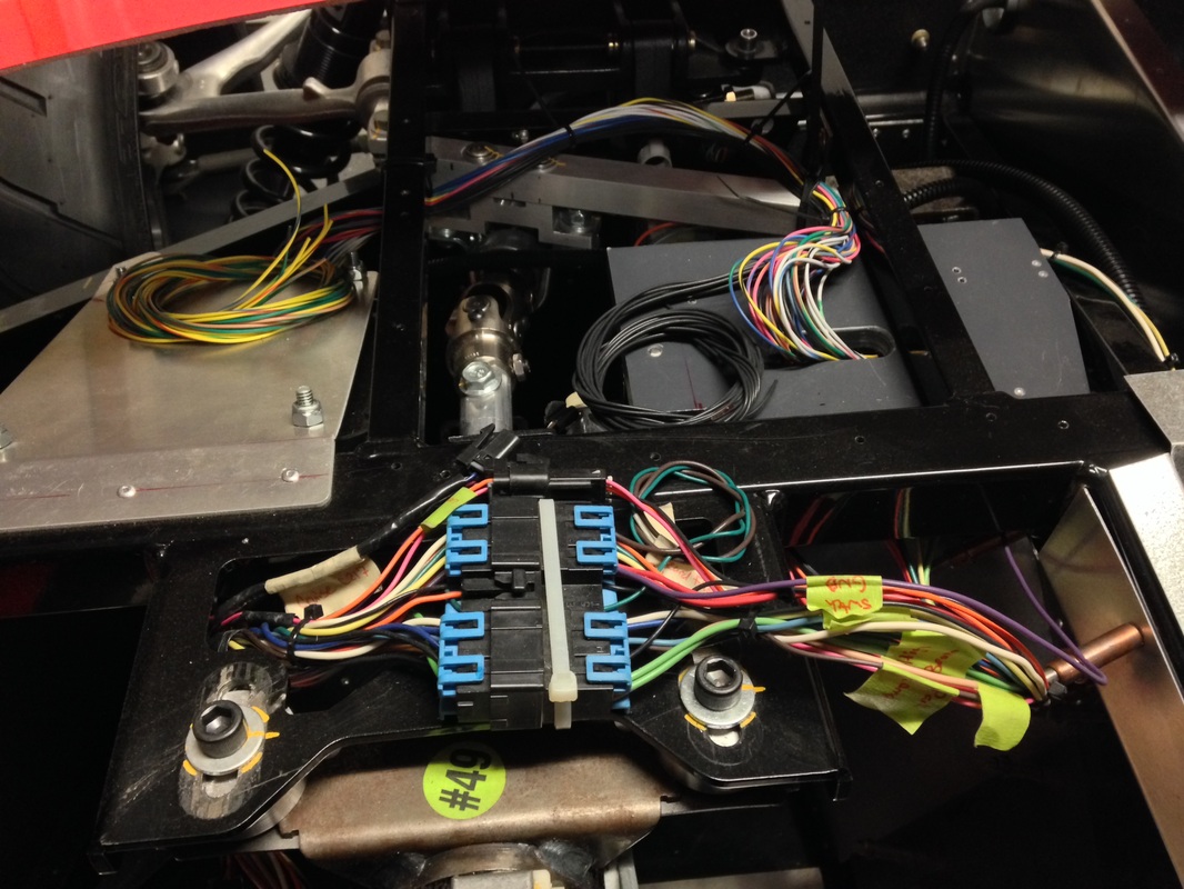
The ISIS system master module takes in all the inputs from various switches (i.e. start, windows, turn signals...etc) in the GTM. The ISIS system comes with connectors for this but I wanted something better for service/trouble shooting. After some serious head scratching I came up with a plan for mounting some terminal strips to a piece of ABS under the dash to the right of the steering column. The input wires from the master module come through a hole in the top of the sheet of plastic and connect to the terminal strips. The inputs from all the switches come from the steering column, center council, brake switch, etc, all very convenient to this location, and connect to the other side of the terminal blocks. The pictures below show the install.
The ISIS system master module takes in all the inputs from various switches (i.e. start, windows, turn signals...etc) in the GTM. The ISIS system comes with connectors for this but I wanted something better for service/trouble shooting. After some serious head scratching I came up with a plan for mounting some terminal strips to a piece of ABS under the dash to the right of the steering column. The input wires from the master module come through a hole in the top of the sheet of plastic and connect to the terminal strips. The inputs from all the switches come from the steering column, center council, brake switch, etc, all very convenient to this location, and connect to the other side of the terminal blocks. The pictures below show the install.

Shifter Cable & wiring Guides
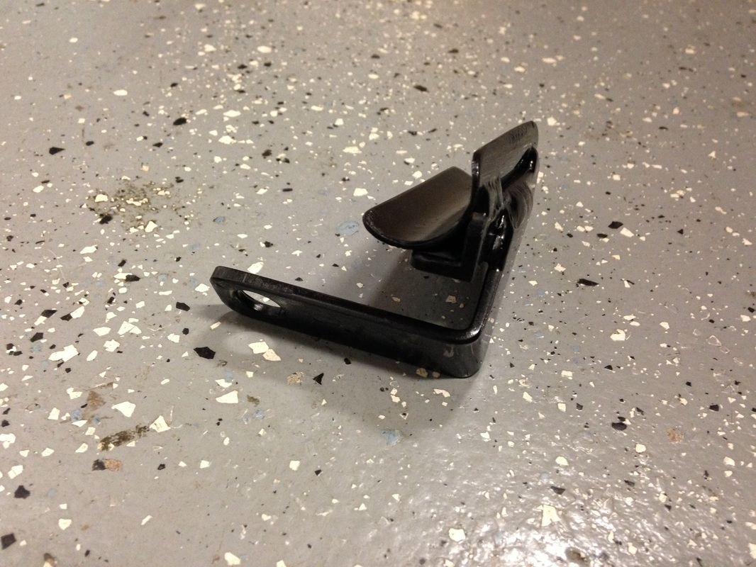
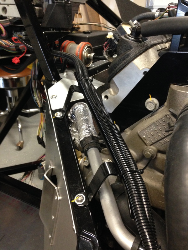
In order to hold the larger of the two shifter cables in the right area as it goes through the engine bay I welded some brackets out of strip, angle and tube. The strip was drilled, bent (in my vise...) and welded to the flat area on the angle. Once this was complete I cut a piece of tubing in half along its axis and welded the half tubes to the angle. Remove all the burrs, notch the back of the angle with a file so the zip ties cant slide off and apply some paint. These were bolted to the cylinder heads in existing threaded holes.
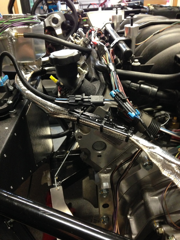
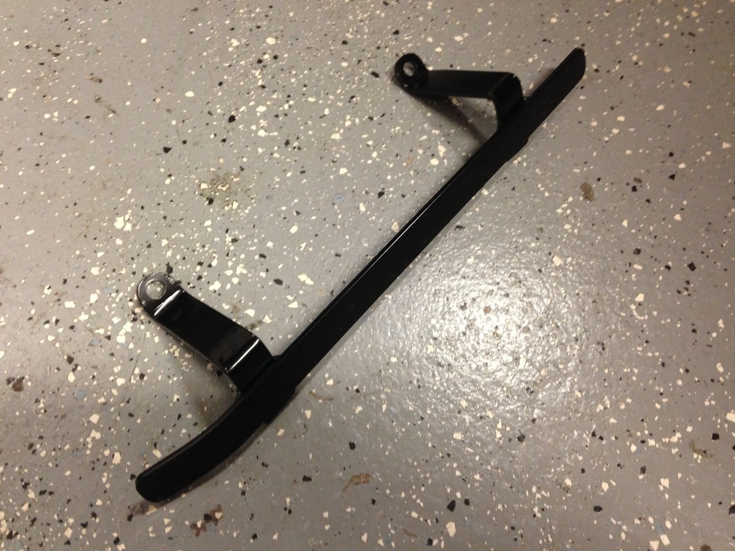
The wire guide was made to hold the two pieces of wire loom coming from the fuse panel area going to the front of the car. This was simply made from strip steel. A little welding, drilling and bending and it was ready for paint.
The wire guide was made to hold the two pieces of wire loom coming from the fuse panel area going to the front of the car. This was simply made from strip steel. A little welding, drilling and bending and it was ready for paint.