11/1/12 to 11/11/12
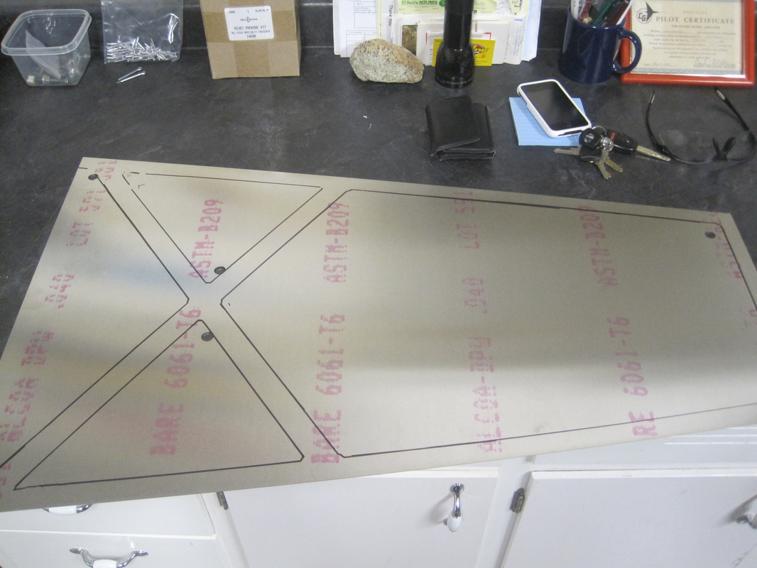
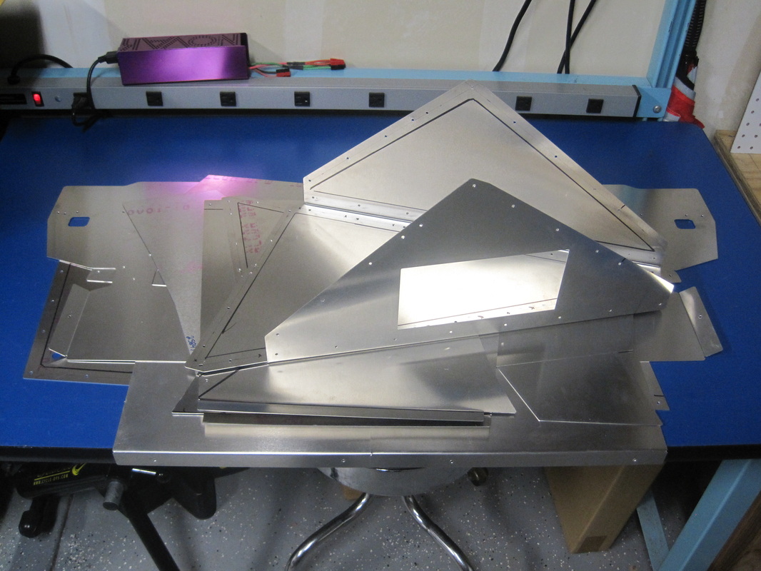
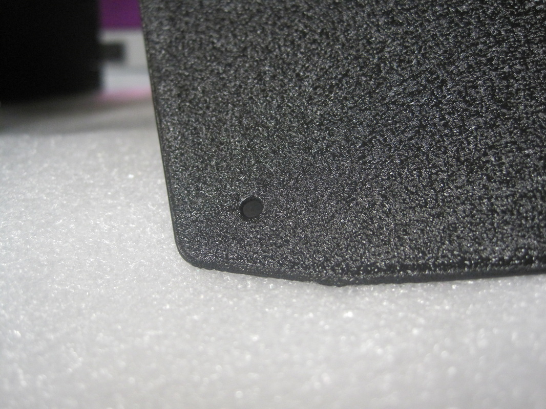
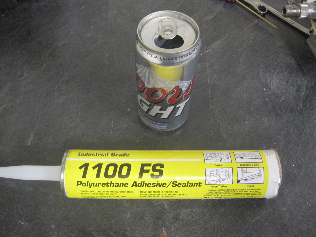
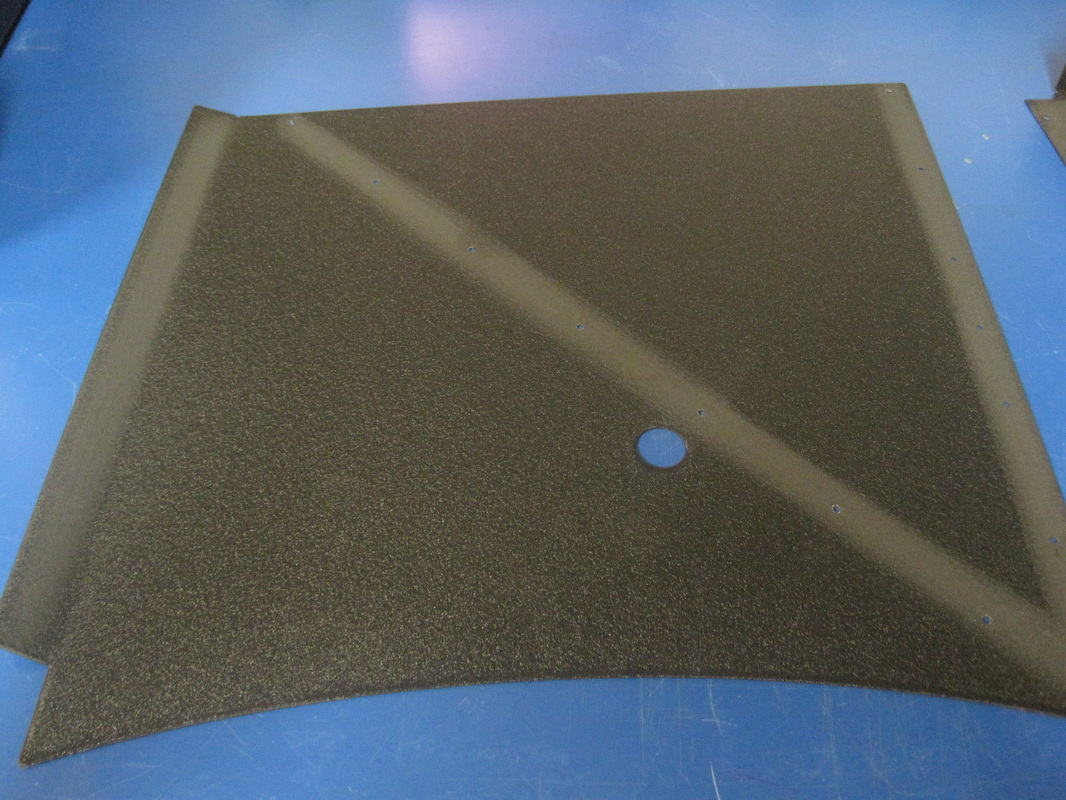
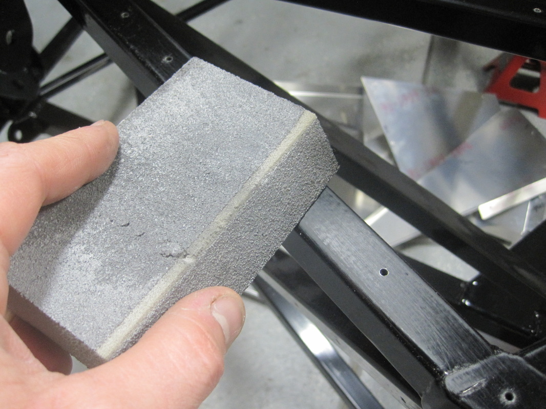
Per the manual the first step is removing the body, tracing the frame onto the aluminum panels, drilling the panels and frame then applying silicon and rivets to hold the panels to the frame. I pretty much followed the manual but planned on powder coating my aluminum panels that will be visible once the build is complete and chose to use a polyurethane adhesive (bought from www.breezeautomotive.com) rather than silicone. Since I didn't want to run to the powder coating guy every day I looked ahead in the manual and ended up preparing about ten panels for my first batch of powder coating. I ended up going with a black crinkle finish which looks really nice. One additional addition was I sanded the frame and panels prior to riveting and bonding them to the frame.
Per the manual the first step is removing the body, tracing the frame onto the aluminum panels, drilling the panels and frame then applying silicon and rivets to hold the panels to the frame. I pretty much followed the manual but planned on powder coating my aluminum panels that will be visible once the build is complete and chose to use a polyurethane adhesive (bought from www.breezeautomotive.com) rather than silicone. Since I didn't want to run to the powder coating guy every day I looked ahead in the manual and ended up preparing about ten panels for my first batch of powder coating. I ended up going with a black crinkle finish which looks really nice. One additional addition was I sanded the frame and panels prior to riveting and bonding them to the frame.


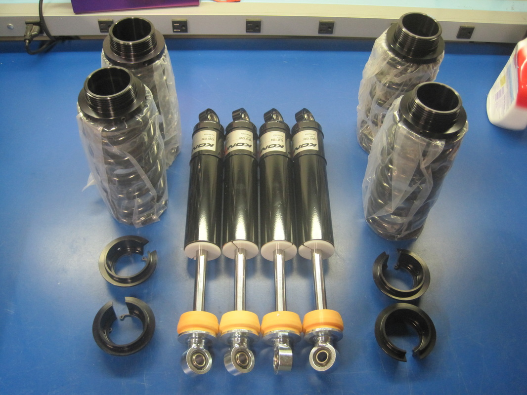
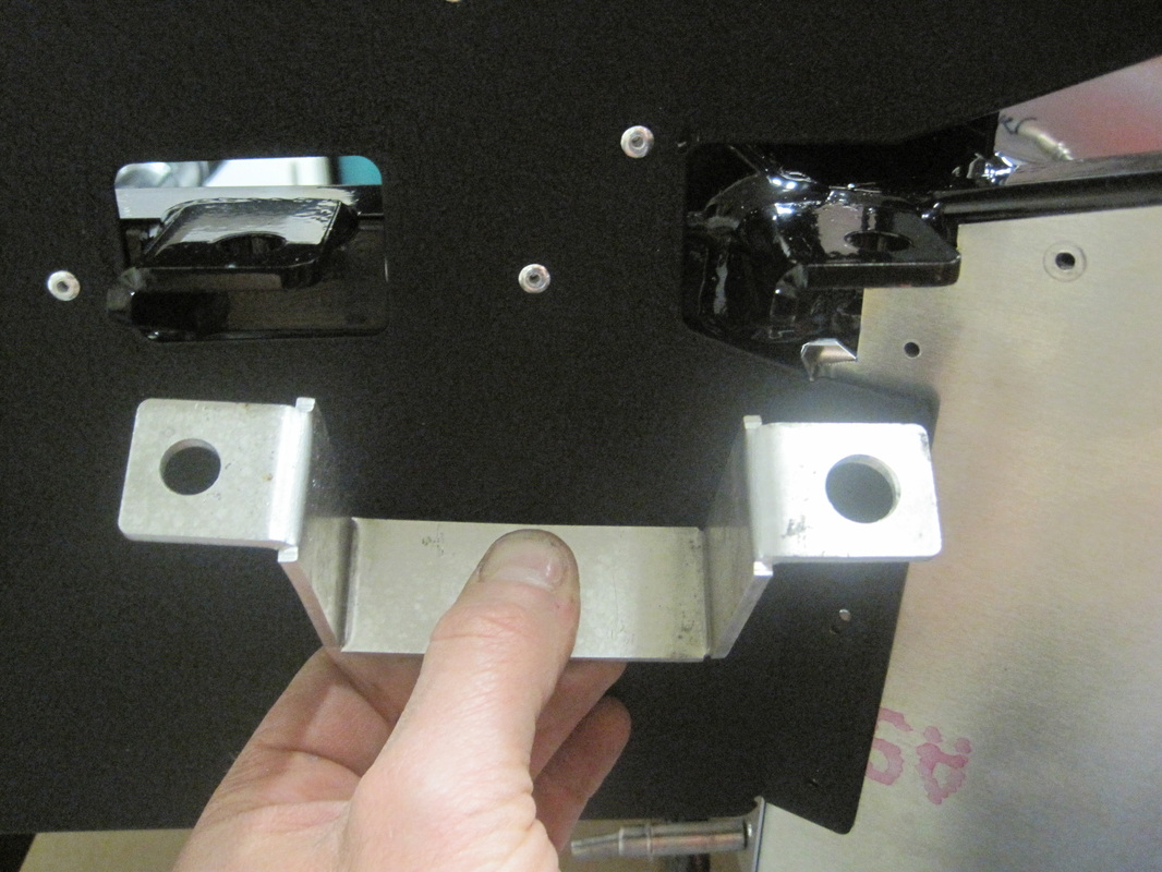
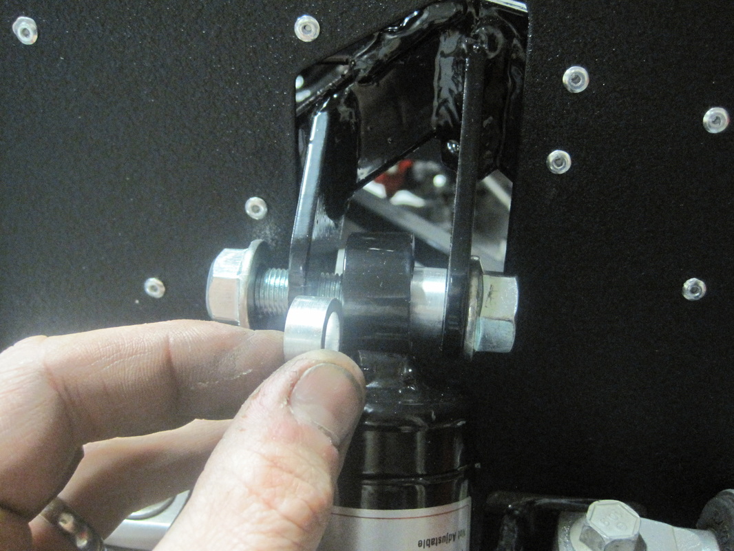
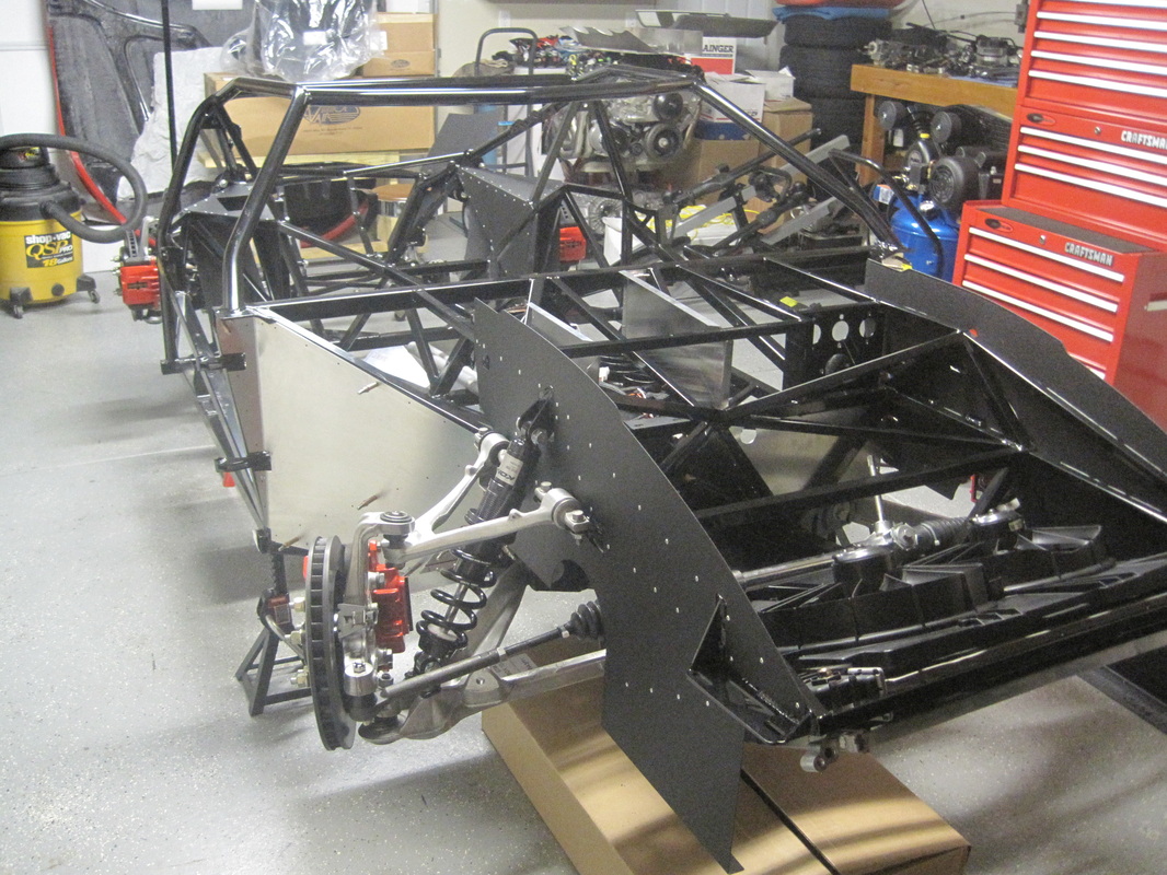
Once I got the first set of aluminum panels on I could mount the donor suspension arms and coil over Koni shocks. This was pretty uneventful other than the aluminum spacers for the front shocks were too long and the brake hose bracket holes did not line up. I ended up trimming the spacers and making the rear hole in the brake hose bracket larger to make the parts fit.
While my first batch of panels was out for powder coating I went ahead and fit up and drilled the aluminum for the foot boxes. One thing I noticed once the suspension was on is it will need to be moved to get all my rivets in as I drilled the holes without the suspension on. Not a big deal but it just made me wait on torquing the suspension bolts up.
While my first batch of panels was out for powder coating I went ahead and fit up and drilled the aluminum for the foot boxes. One thing I noticed once the suspension was on is it will need to be moved to get all my rivets in as I drilled the holes without the suspension on. Not a big deal but it just made me wait on torquing the suspension bolts up.

11/12/12 to 11/18/12
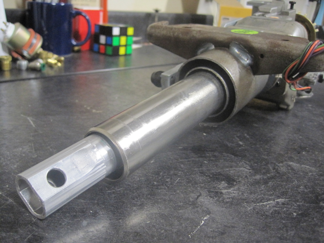
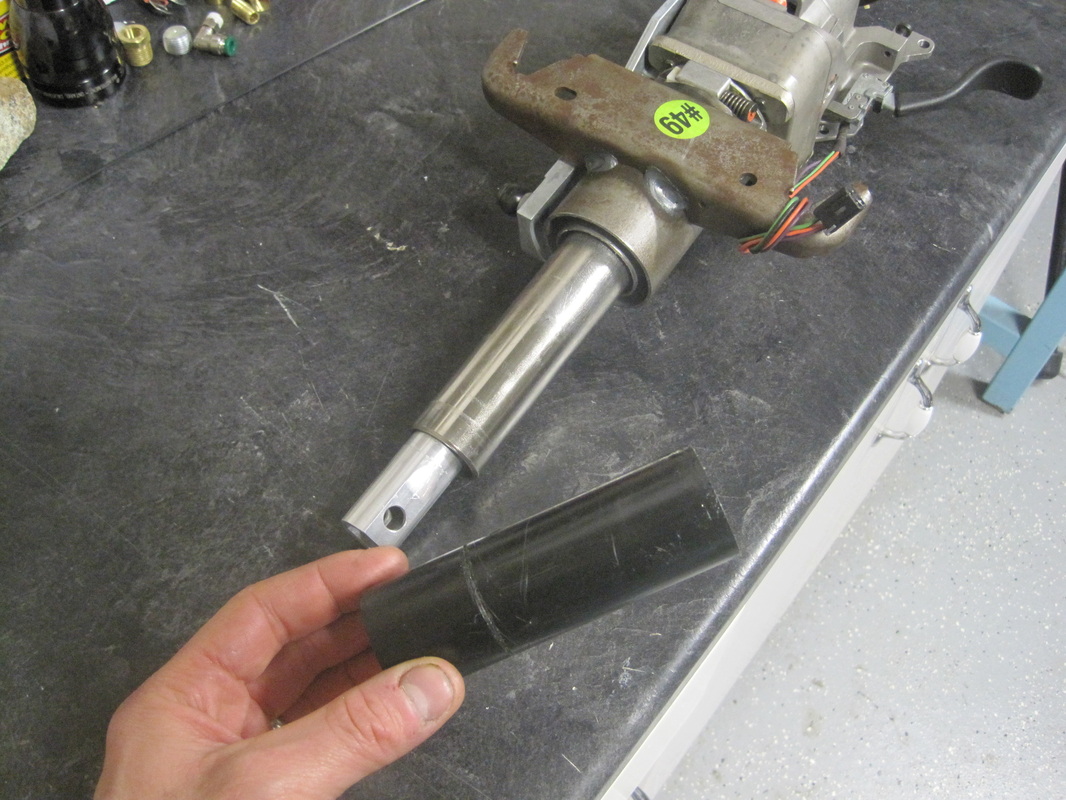
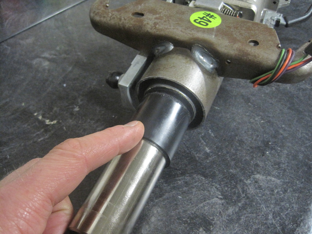
This week I worked on the steering. Getting the Corvette column apart was a bit of a challenge but with some guess work and help from the GTM manual it came apart. I did end up picking up a steering pivot pin puller from Napa which made pulling the pins easy. Once the column was apart I completed the modifications per the manual and put it back together.
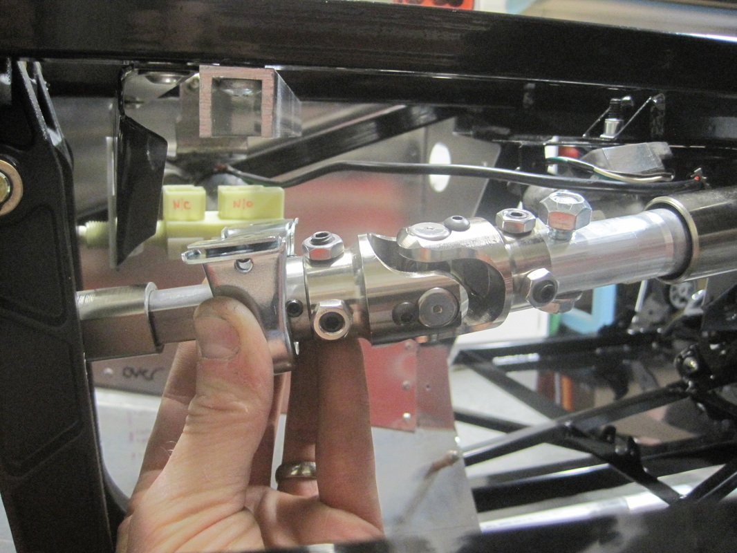
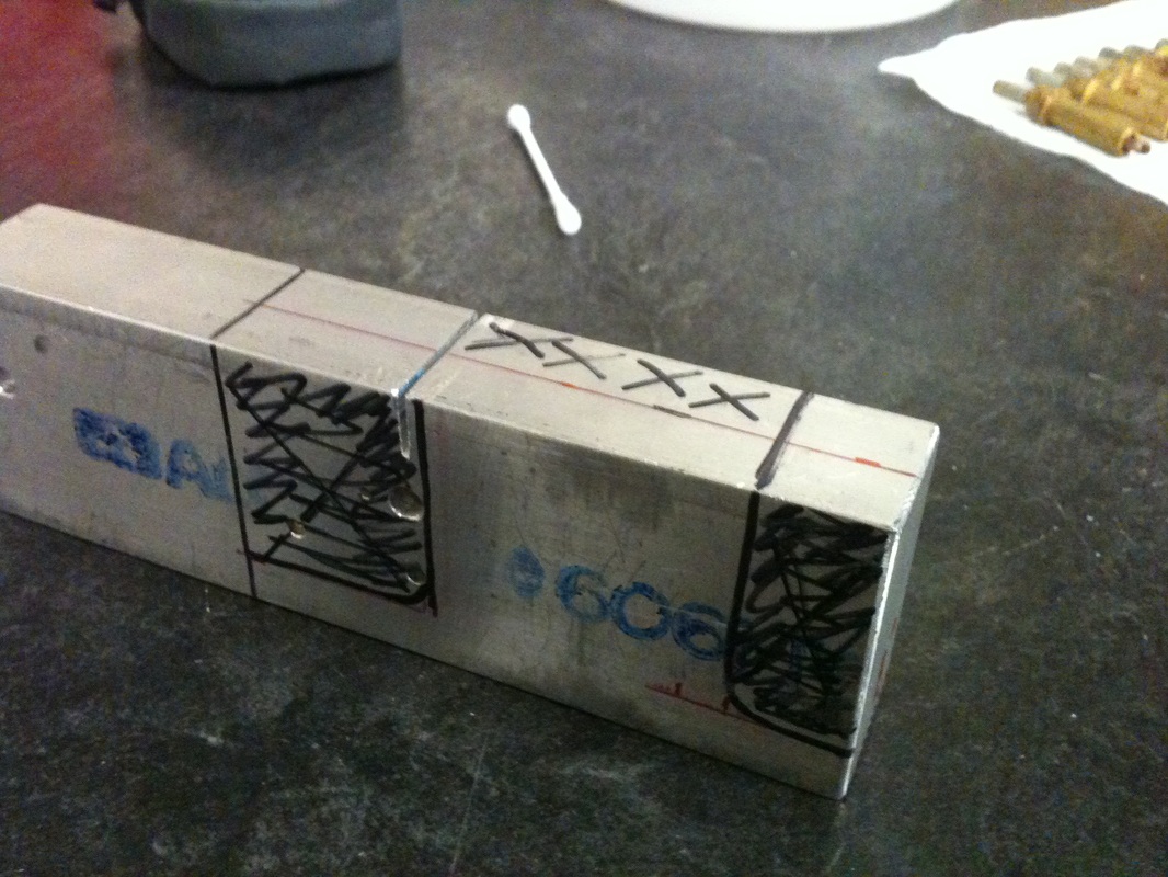
After the column was ready I cut a piece of 3/4" "D" shaft 1 7/8" long and put dimples into it so the set screws had a place to nest into. This makes a more secure connection between the set screws and the 3/4" "D". I also put these dimples into the piece of 3/4" "D" that is pinned to the steering shaft with the two universals. A couple of vids down shows the shafts with the dimples.
This week I worked on the steering. Getting the Corvette column apart was a bit of a challenge but with some guess work and help from the GTM manual it came apart. I did end up picking up a steering pivot pin puller from Napa which made pulling the pins easy. Once the column was apart I completed the modifications per the manual and put it back together.
After the column was ready I cut a piece of 3/4" "D" shaft 1 7/8" long and put dimples into it so the set screws had a place to nest into. This makes a more secure connection between the set screws and the 3/4" "D". I also put these dimples into the piece of 3/4" "D" that is pinned to the steering shaft with the two universals. A couple of vids down shows the shafts with the dimples.


11/19/12 to 11/30/12
These last couple weeks I have completed the steering, the computer mount, mounted the parking break assembly, mounted the pedal box and mounted the brake light switch.
Steering:
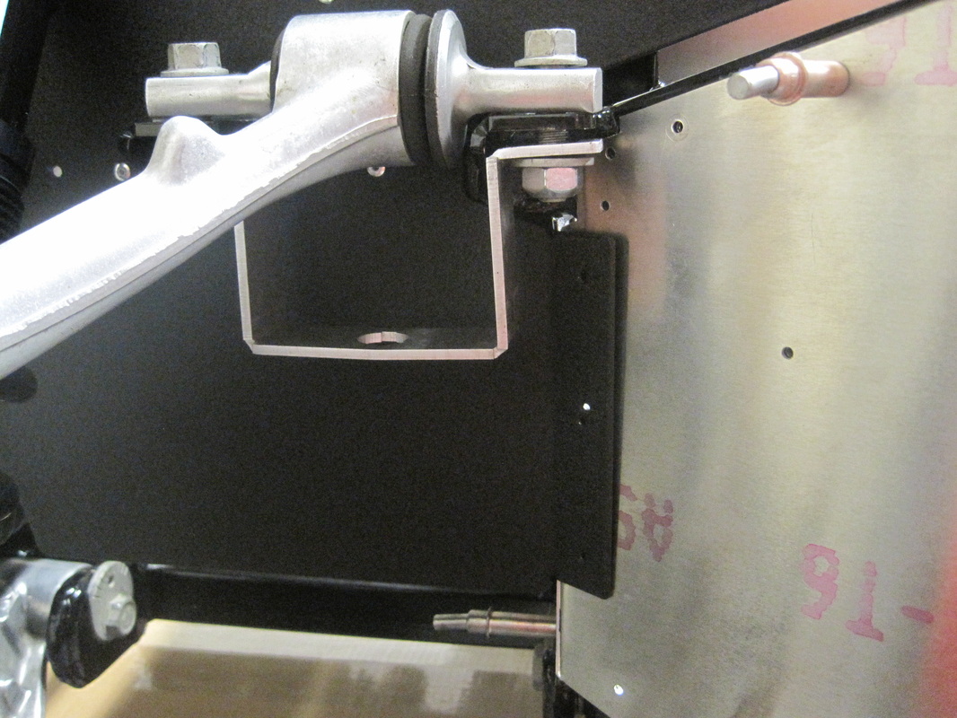
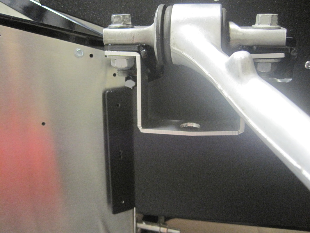
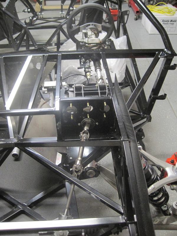
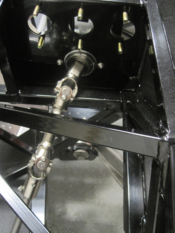
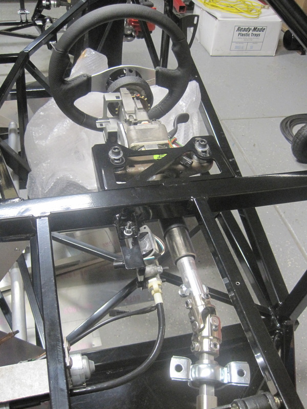
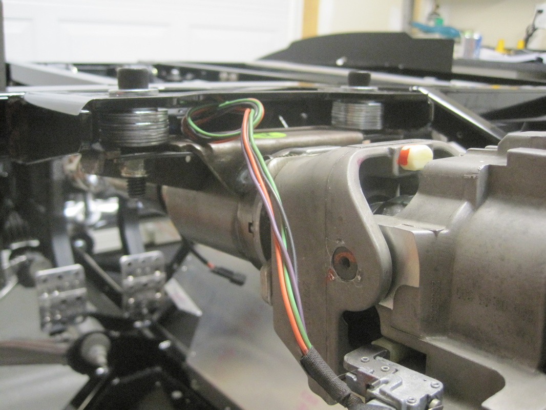
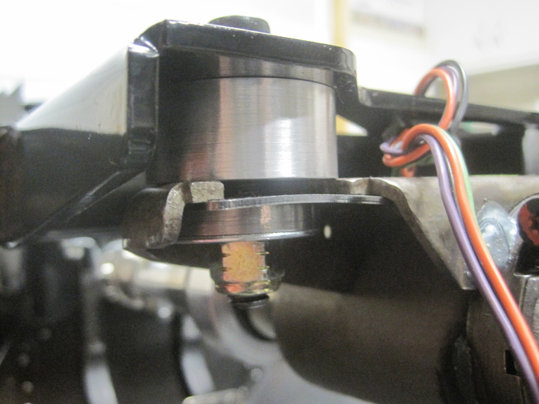
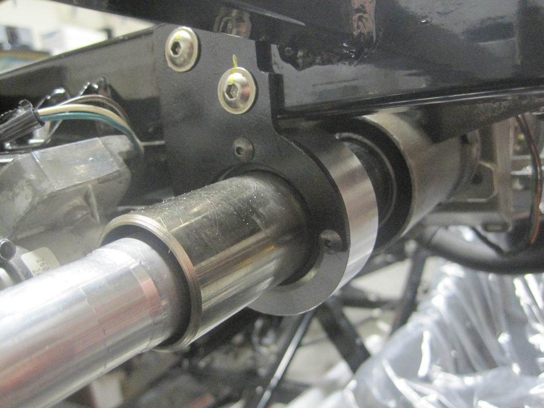
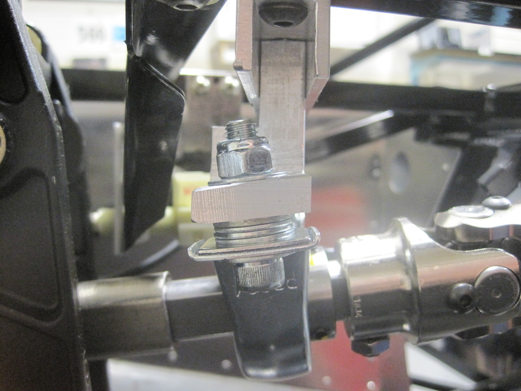
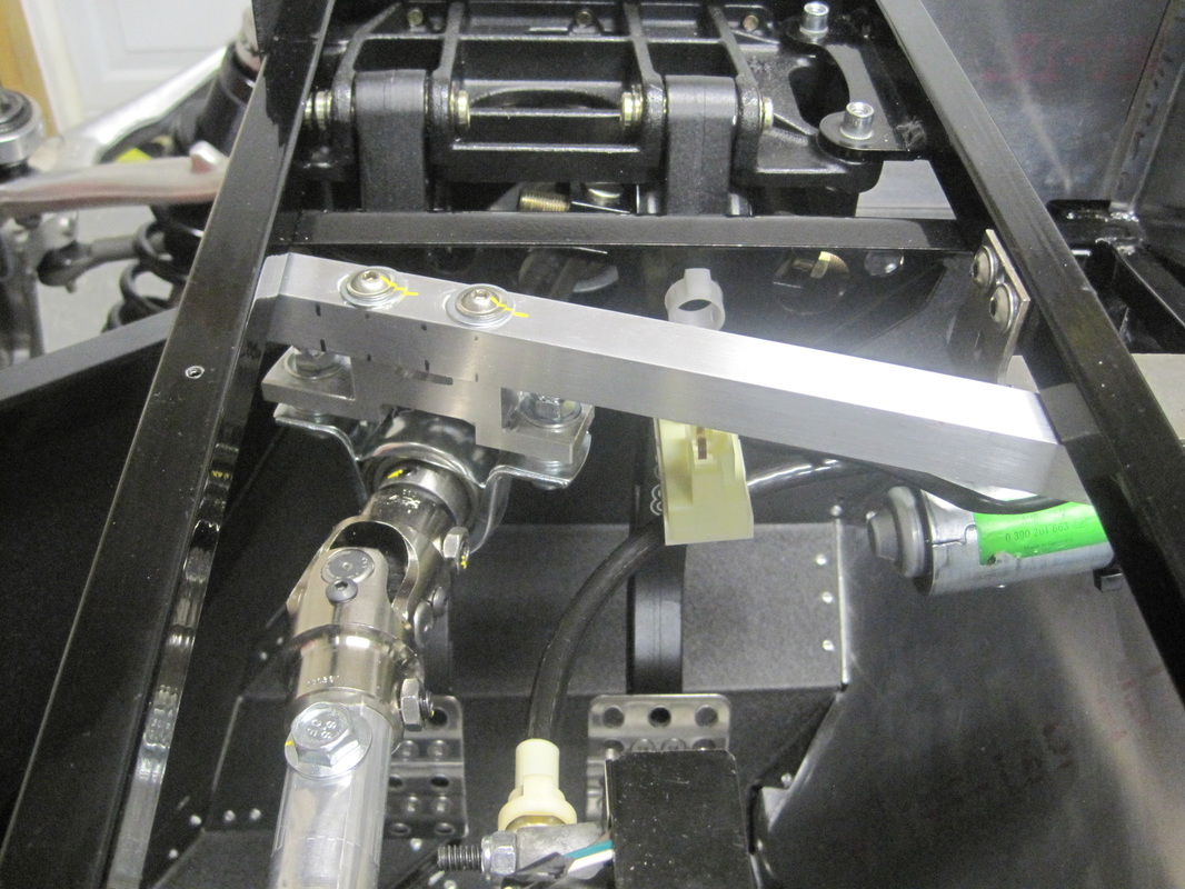
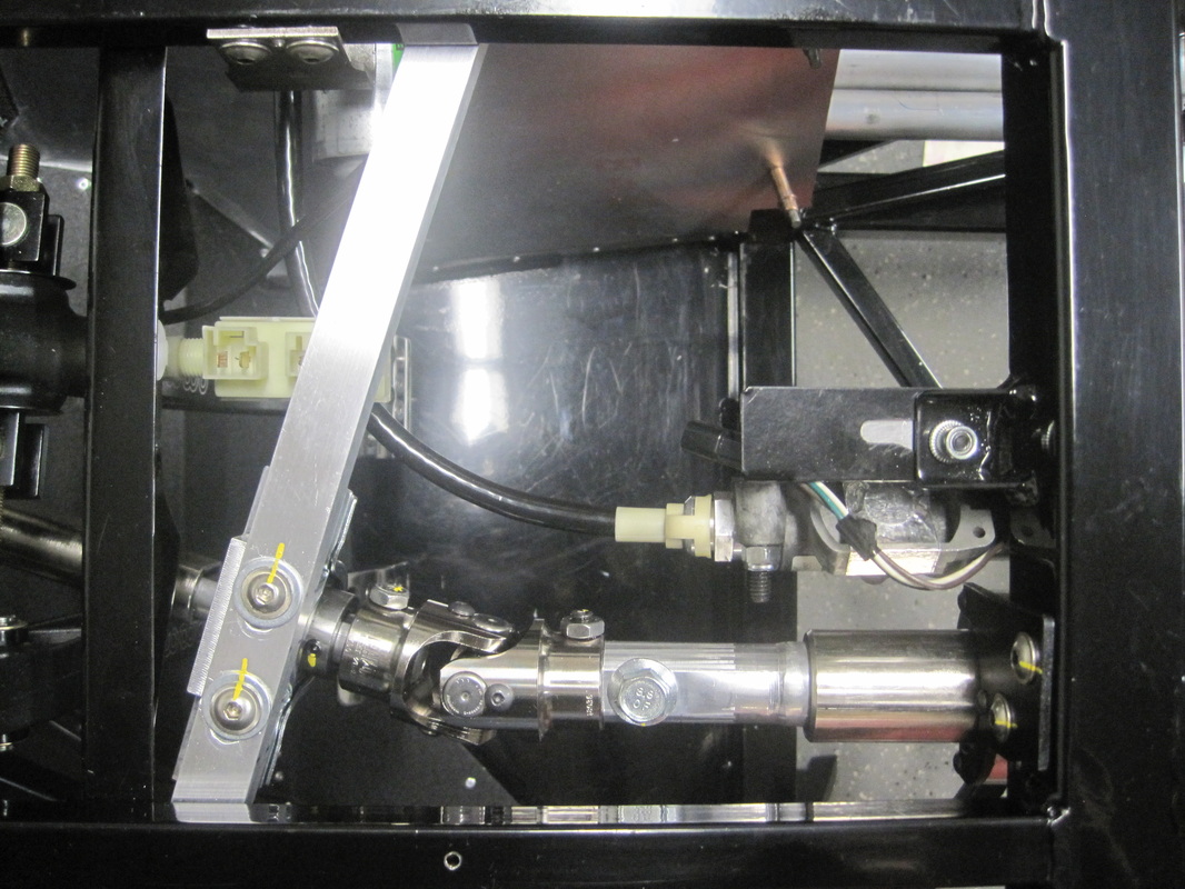
The steering required a fair amount of work and quite a few custom parts. The pictures and video show the parts I made including the spacers to drop the column so it would line up with the telescopic actuator, .200 thick steel washers that don't bend when the bolts are tightened, a column support bearing to give the steering wheel a solid feel and a pillow block mount that makes up for the lack of a mount in the kit.
These last couple weeks I have completed the steering, the computer mount, mounted the parking break assembly, mounted the pedal box and mounted the brake light switch.
Steering:
The steering required a fair amount of work and quite a few custom parts. The pictures and video show the parts I made including the spacers to drop the column so it would line up with the telescopic actuator, .200 thick steel washers that don't bend when the bolts are tightened, a column support bearing to give the steering wheel a solid feel and a pillow block mount that makes up for the lack of a mount in the kit.


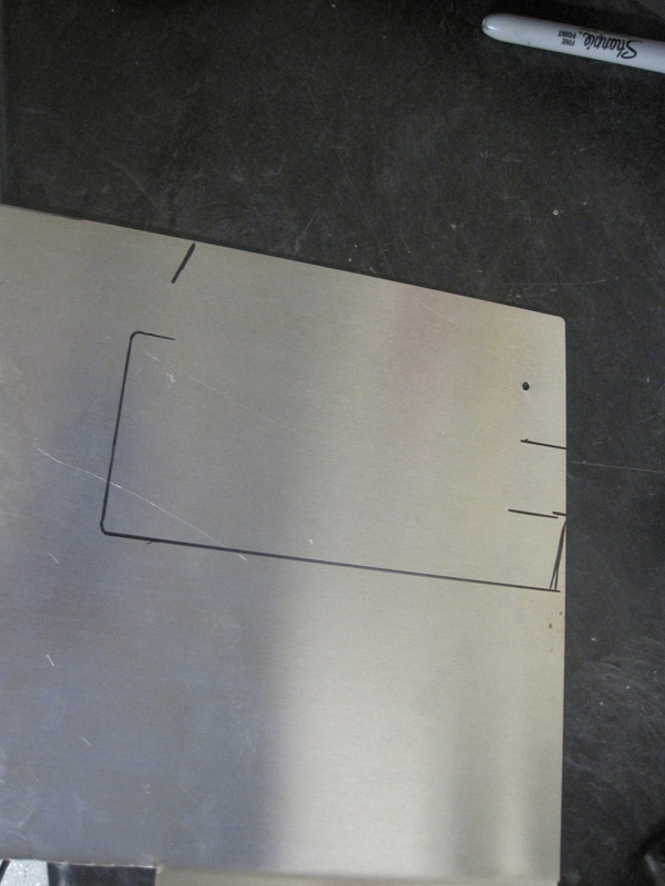
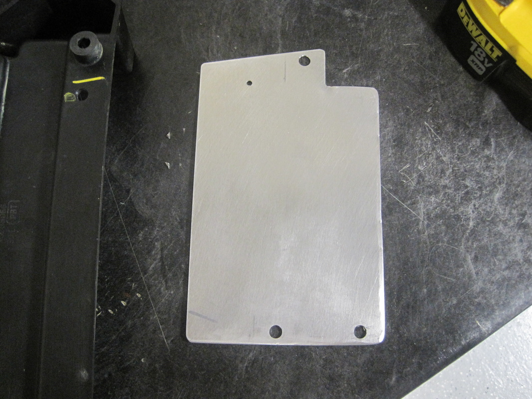
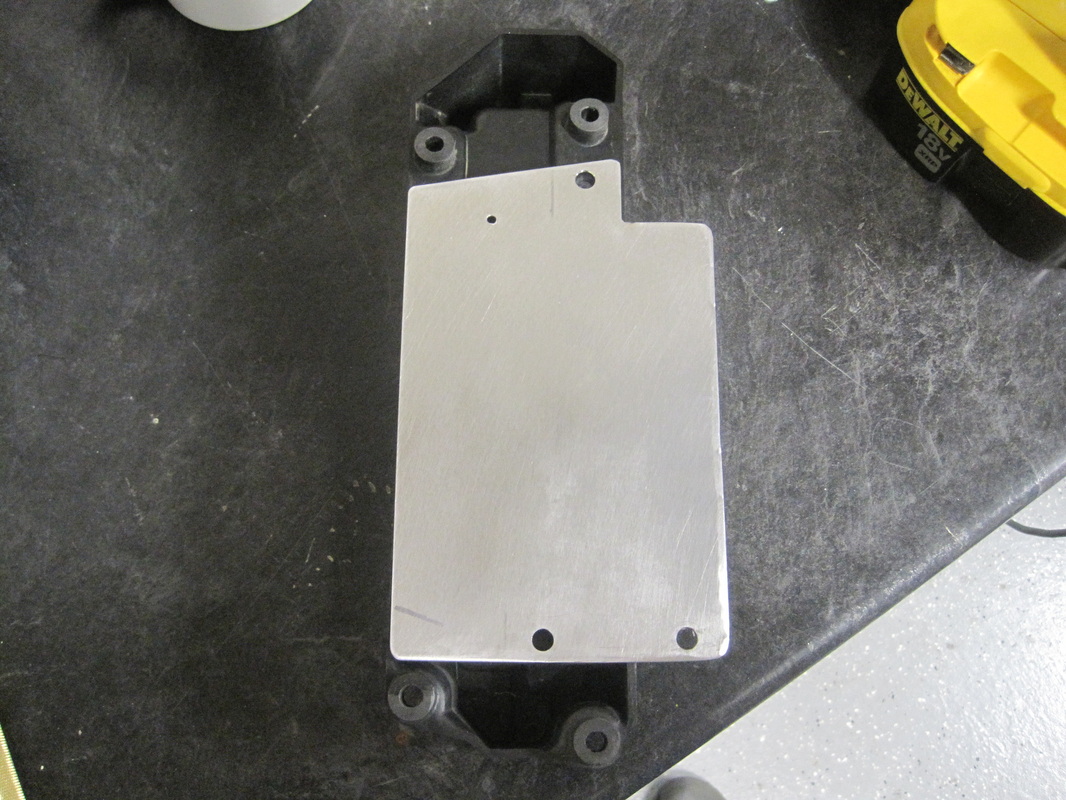
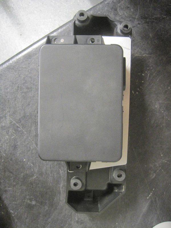
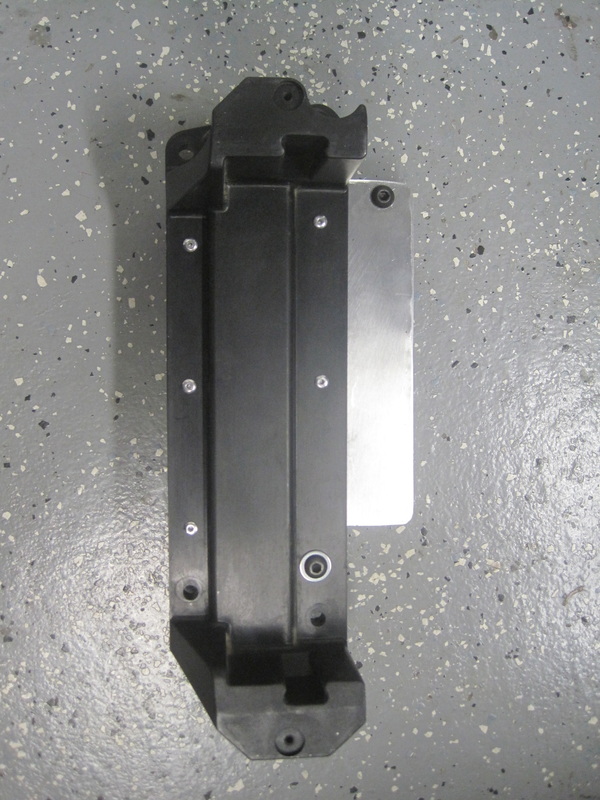
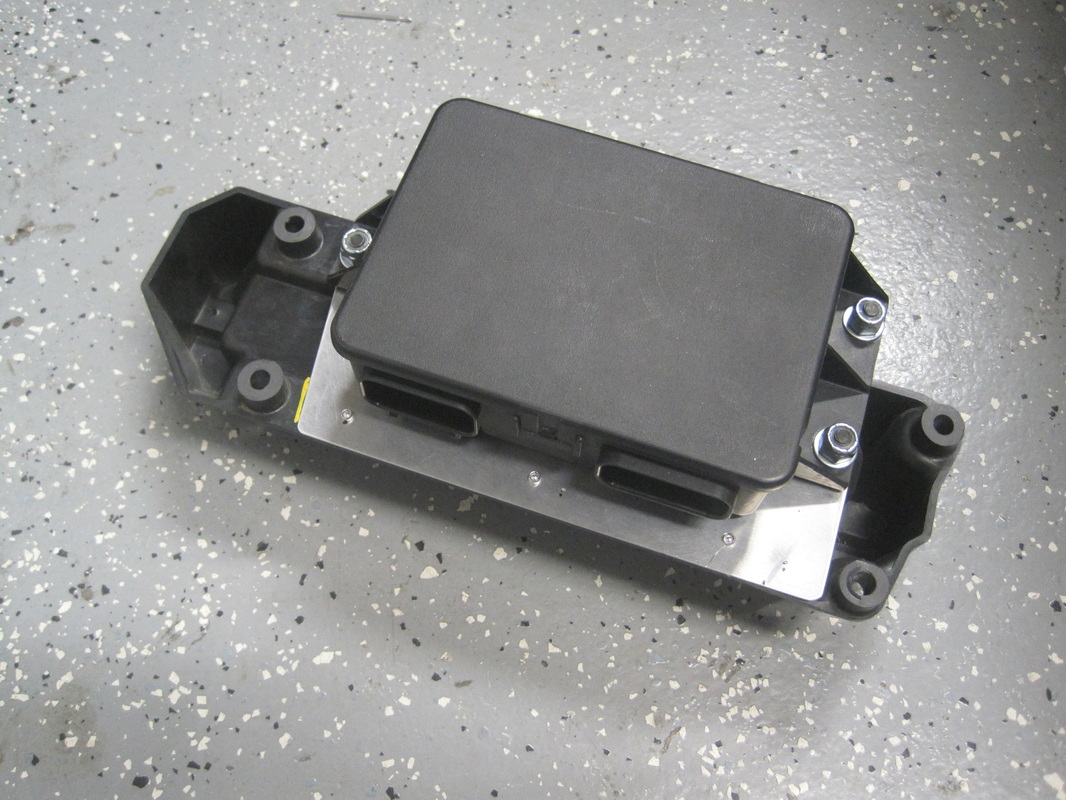
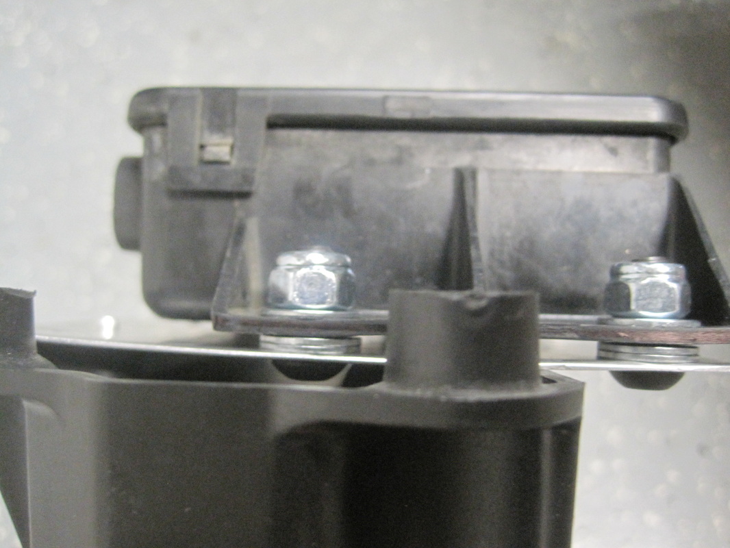
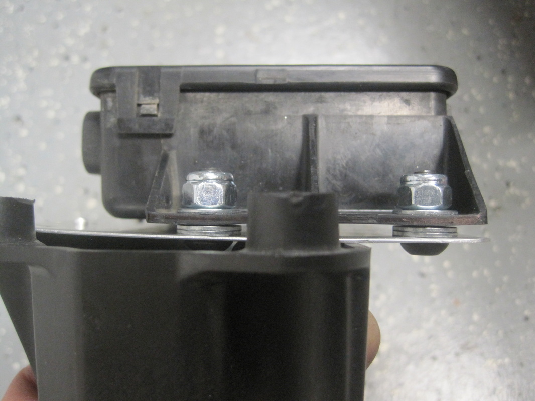
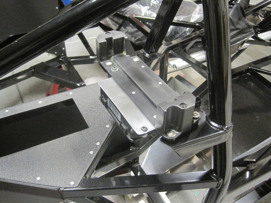
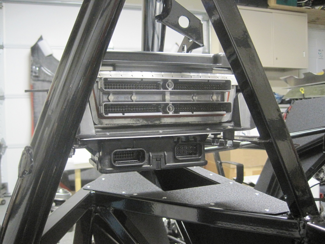
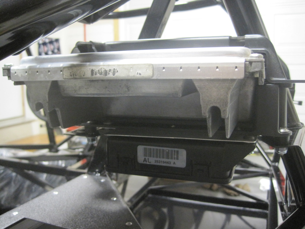
PCM Mount:
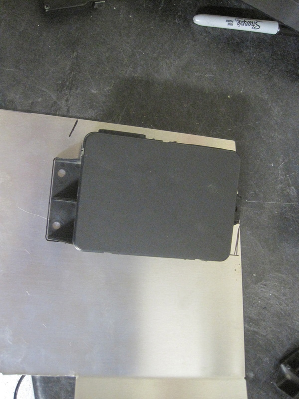
I made a mounting plate for my TAC module since the mounting holes on the module didn't line up with flat areas on the plastic PCM mount. The plate I made ended up being held to the PCM mount with TAC module mounting bolts and rivets. I spaced the TAC module away from the plate I made so the rivets had room to protrude through.
I made a mounting plate for my TAC module since the mounting holes on the module didn't line up with flat areas on the plastic PCM mount. The plate I made ended up being held to the PCM mount with TAC module mounting bolts and rivets. I spaced the TAC module away from the plate I made so the rivets had room to protrude through.
Pedal Box:
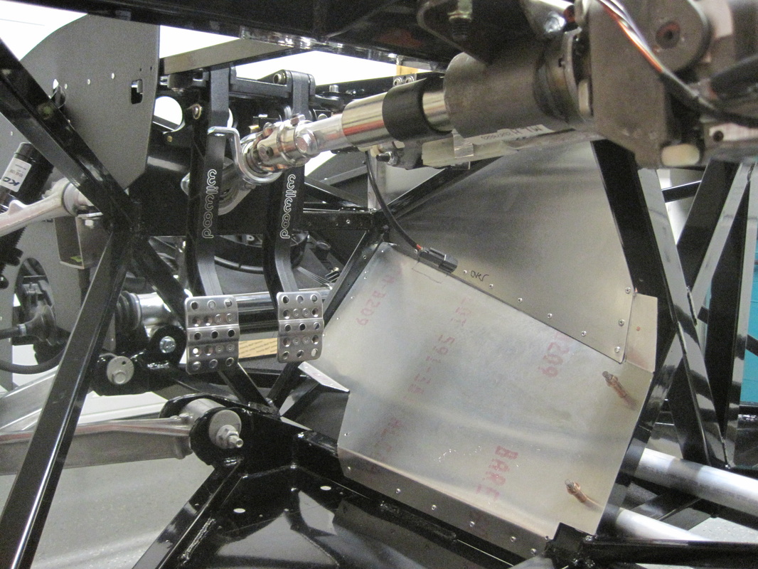
When I put my pedal assembly in I noticed the pedals squeeked when pushed. Upon further inspection all the pivot points on the pedal assembly were bone dry (no lubrication). I ended up taking the pedal box apart and greasing every pivot point. No more squeeking here!!
Another mod I did involved putting in a 5/8" bore master cylinder in for the clutch. I did some reading on the forum and this makes the pedal effort easier and may even eliminate the need for a pedal travel limiter. Some times the travel limiter is needed to avoid over traveling the slave cylinder and damaging the transmission.


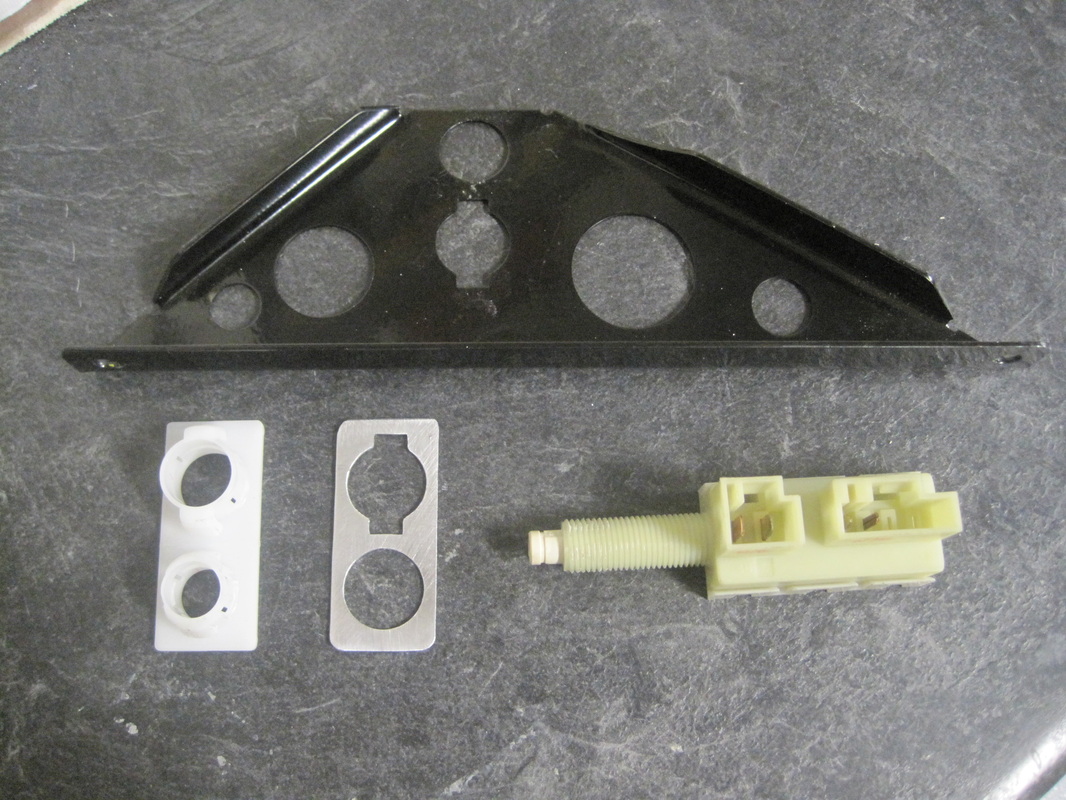
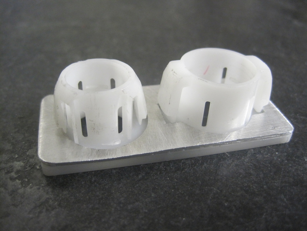
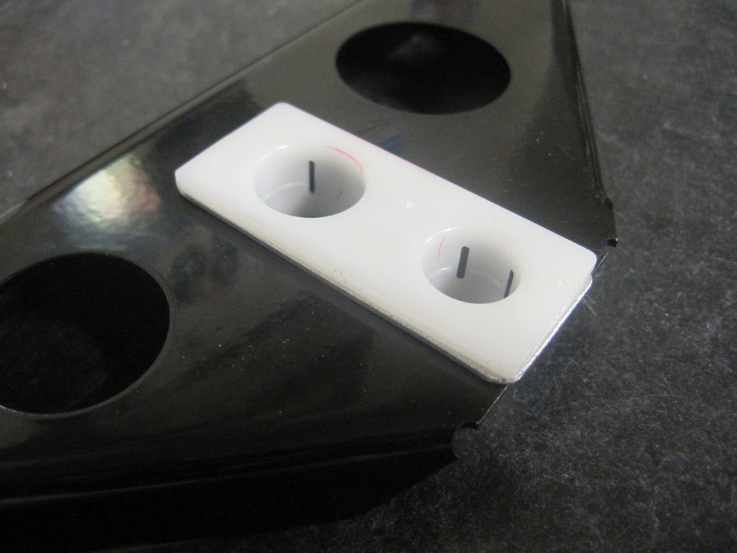
Brake Switch Mount:
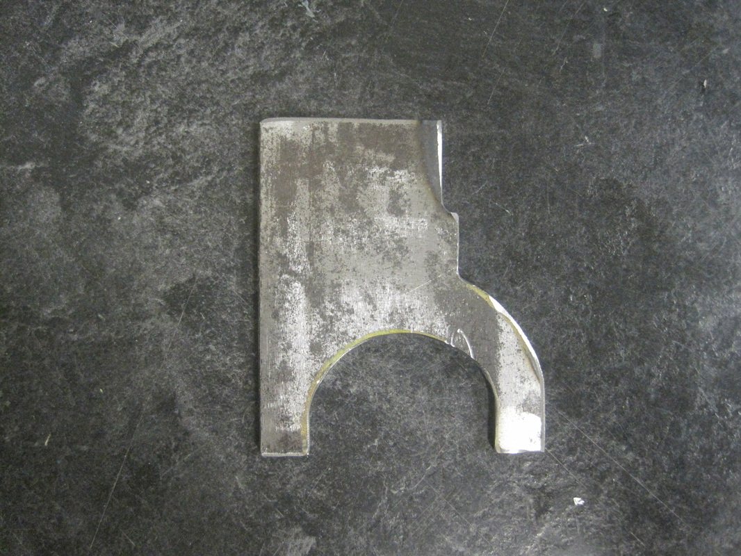
When I mounted the brake light switch I noticed the white plastic piece from donor C5 fit loosely in the FFR supplied mounting plate (black). To make it a better fit I traced the plastic piece onto a scrap piece of sheet metal from the GTM kit and proceeded to make a spacer with tin snips, a uni-bit and a small file. After I added the spacer the parts fit together much better.
When I mounted the brake light switch I noticed the white plastic piece from donor C5 fit loosely in the FFR supplied mounting plate (black). To make it a better fit I traced the plastic piece onto a scrap piece of sheet metal from the GTM kit and proceeded to make a spacer with tin snips, a uni-bit and a small file. After I added the spacer the parts fit together much better.